
7-AXIS / RESEARCH MANIPULATOR

Atlas A7

Configured per project

Lightweight 7-Axis Research Arm

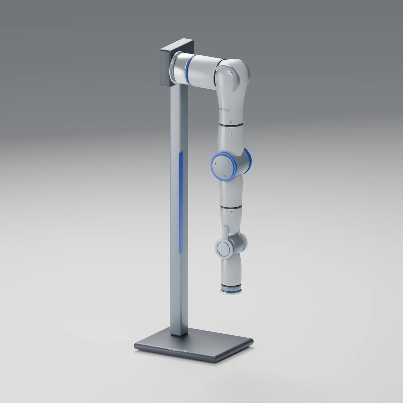
A lightweight 7-DOF arm for fixed-workstation manipulation and robot learning. Redundant kinematics, hand-guided teaching and hybrid force-position control support research on obstacle-aware planning, demonstration capture, impedance control and imitation learning. Choose a left arm, right arm or dual-arm set per task.

7 axesRedundant degrees of freedom
3 kgMax end-effector payload
739.45 mmMax reach
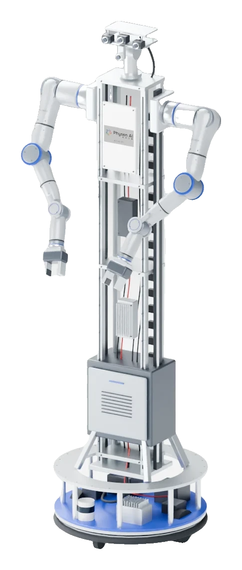
PHYSEN AI +Atlas A7, Stand for display only · Single-arm and dual-arm configurations ordered separately
Stand for display only · Single-arm and dual-arm configurations ordered separately
From a single device to a complete solution.

Data outputs, interface adaptation and delivery scope are confirmed per task.

Robot Learning Workstation
01

One more degree of freedom, one more way to plan

The anthropomorphic 7-axis configuration opens up research on end-effector pose holding, joint obstacle avoidance and redundancy resolution. At 4.3 kg per arm with a rated repeatability of ±0.1 mm, it suits lab benches and fixed workstations.
02

Hand-guided teaching that records real execution

The manual lists gravity compensation, zero-force hand guiding and trajectory playback, with a 100 Hz teaching sampling rate, recording joint position, velocity and torque-related data. Sampling rate is not control frequency, and torque readings are not end-effector contact force.

03

From low-level control to your research toolchain

Joints support position, velocity, torque and MIT hybrid control. Developer resources cover the Python / C++ SDK, ROS 2 Humble, MoveIt2, Gazebo and URDF; driver versions, interfaces and examples are confirmed per project.

ATLAS A7 / IN THREE DIMENSIONS

The 7-axis profile, up close from every angle.

Drag to inspect the shoulder, elbow, wrist and end interface, switch between front, side and back, and zoom in on A7 structural details.

One product, three ways to see it.
3D MODEL ATLAS A7
ATLAS A7 product imageLoading 3D model…
Drag to rotate · Scroll / pinch to zoom · Arrow keys

DIMENSIONS & INTERFACES

From workspace to every mounting interface.

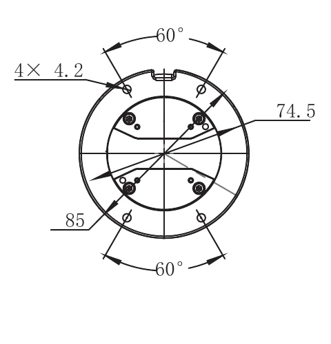
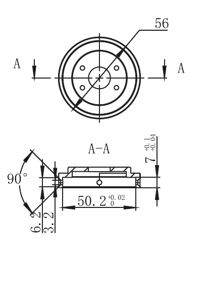
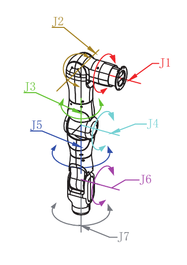
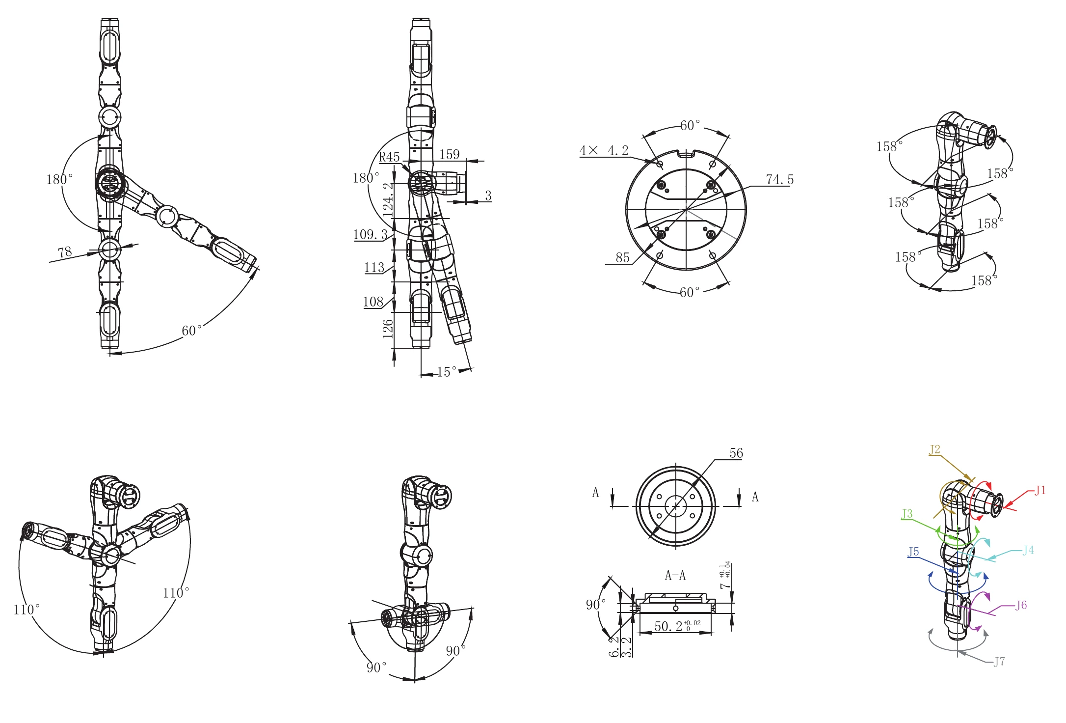
Original brochure dimension drawings, viewed separately for the whole arm, shoulder, end and joint numbering. The product exterior is gray-blue; engineering drawings keep their original annotations.

ATLAS A7 / Dimensions and range of motionMANUAL · PAGE 04
Atlas A7 dimensions and range of motion, with the brochure's dimensions, angles and tolerances
Original dimension drawings from the product manualView original drawing

Source: 7-axis arm product manual, dimension drawing page (PAGE 04). This page supports selection and integration discussions; use the formal engineering drawings and models for your version for machining, mounting and collision checks, and do not measure from web images.

READY FOR YOUR WORKBENCH

Bring the arm into your experiment workflow.

Confirm mounting and power first, then drivers, zero points and teaching records, building reproducible manipulation experiments step by step.

Fixed-workstation mounting

Left arm / right arm / dual arms

Select per task and check the shoulder mounting surface, end interface and workspace. Rated weight is 4.3 kg per arm and rated max end payload is 3 kg.

Power and communication

DC 48 V · CAN 2.0

The manual requires a supply of at least 6 A. CAN runs at 1 Mbps and connects to the workstation via USB-to-CAN; adapter and cables are supplied per the configuration list.

Development and simulation

ROS 2 Humble

Ubuntu 22.04 LTS recommended. The toolchain includes the Python / C++ SDK, MoveIt2, Gazebo and URDF, with versions and license scope confirmed per project.

Hand-guided teaching and recording

100 Hz teaching sampling

Hand-guide the arm at low speed with zero-force control and gravity compensation, recording joint position, velocity and torque-related data, with trajectory playback. Sampling rate is not control frequency.

First power-on and teaching

Make sure the range of motion is clear and check zero points and safety boundaries. Hand-guided teaching requires zero-force control to be enabled correctly; never force the arm when powered off or with brakes engaged. High-speed or contact tasks need end-effector protection and risk controls validated first.

THE DETAILS MATTER

Every detail, spelled out.

Key Atlas A7 specifications below; choose left, right or dual-arm configurations.

Structure and performance

ParameterSpec / configuration
Degrees of freedom7 axes (7-DOF)
Weight per arm4.3 kg
Max end-effector payload3 kg
Max reach739.45 mm
Repeatability±0.1 mm
MaterialsAluminum alloy frame, plastic housing
MountingFixed workstation; mounting surface must be level and rigid, hole pattern per the drawing for your version
OptionsLeft arm / right arm / dual-arm set

Max payload is not a guarantee at every pose; end-tool mass, center of gravity and dynamic conditions must be included in selection. Repeatability is not absolute accuracy.

7-axis joint parameters

JointRange of motionMax speedRated torquePeak torque
J1-60° to +180°180°/s15 N·m30 N·m
J2-180° to +15°180°/s15 N·m30 N·m
J3±158°180°/s15 N·m30 N·m
J4±110°180°/s15 N·m30 N·m
J5±158°180°/s3 N·m7 N·m
J6±90°180°/s3 N·m7 N·m
J7±158°180°/s3 N·m7 N·m

J1–J4 are the upper-arm joints and J5–J7 the wrist joints. Values are from the manual; coordinates, zero points and sign conventions for left and right arms follow the corresponding driver and mounting version. Peak torque is not continuous output.

Power, communication and control

ParameterSpec / configuration
Power supplyDC 48 V; the manual requires a supply of at least 6 A, with headroom for actual operating conditions
Total power<300 W
CommunicationCAN 2.0, 1 Mbps; via the supplied USB-to-CAN adapter
External portsPower port × 1, CAN port × 1
Joint encoders21-bit dual encoders
Joint control modesPosition / velocity / torque / MIT hybrid control
TeachingGravity compensation, zero-force hand-guided recording, trajectory playback
Teaching sampling rate100 Hz
Teaching recordsJoint position, velocity and torque-related data; fields, units and timestamps checked against the SDK version

The joint modules' wide voltage range does not replace the system's DC 48 V supply requirement. Neither the CAN bus rate nor the teaching sampling rate equals policy inference or end-to-end control frequency.

Software and research integration

ParameterSpec / configuration
Recommended development environmentUbuntu 22.04 LTS
Development interfacesPython / C++ SDK; specific APIs and examples per the delivered version
Robot middlewareROS 2 Humble driver package
Motion planningMoveIt2
Simulation and modelsGazebo, URDF and controller configs; models must match the physical robot version
Engineering documentationMounting and end-effector interface documentation available per project, with version and license confirmed
Data Engine integrationVision, joint state, action commands and task events can be paired per project, with sync and export validated separately
Training and inferenceCan be paired with an external workstation or cloud service; no built-in GPU, model or pre-trained skills by default

Available versions and licenses of software, models and drawings are checked item by item. Third-party developer resources are not presented as our own work, and a complete open-source project is not delivered by default.

Environment and configuration

ParameterSpec / configuration
Operating temperature5–50 °C
Relative humidity35%–80% RH, non-condensing
Noise<60 dB (measurement conditions not stated in the manual)
Arm optionsSingle left arm, single right arm or dual-arm set; quantity and mounting direction specified in the order
AccessoriesUSB-to-CAN module, USB cable, power and CAN cables, mounting fasteners and tools, delivered per the configuration list
Confirmed separatelyWhether a power adapter, gripper, tactile end effector, cameras, fixtures, workstation and safety components are included

FROM CAPTURE TO ARCHIVE

From power-on to a complete data episode.

  1. 01

    Confirm task and mounting

    Decide single or dual arm, end-effector mass and center of gravity, workstation space and safety boundaries; check mounting rigidity and power.

  2. 02

    Teach and record paired data

    Check zero points, drivers and gravity compensation, and capture demonstrations under safe conditions; when vision is used, record calibration and timing alongside.

  3. 03

    Train, replay and evaluate on the robot

    Validate slow-speed trajectory playback first, then evaluate policies on agreed tasks, keeping human takeover, failure and exception logs.

CONFIGURE. VERIFY. DELIVER.

From selection to delivery,
make the configuration clear.

View solutions
  • Confirm left/right arm versions, arm count, end effector, mounting stand, power and USB-to-CAN setup, and freeze the delivery list.
  • Provide the matching drivers, SDK examples, models and version notes; software licenses and technical support scope are confirmed item by item per project.
  • Validate zero points, limits, emergency stop and connection-loss handling. Zero-force hand guiding must be done in the correctly enabled mode; never force the arm when powered off or with brakes engaged.
  • Accept teaching records, trajectory playback and agreed tasks under the actual mounting, payload and speed conditions; a spec sheet never replaces system safety and task validation.

START WITH YOUR TASK

Tell us about your research task.

From device selection to data and training workflows, we'll help you find the right place to start.

Contact us