Five-finger form, six-channel control
The thumb has one lateral and one longitudinal channel, and the other four fingers each control flexion. Phalanges are mechanically linked, so each visible phalanx is not an independently actuated DOF.


DEXTEROUS HAND / 6 DOF
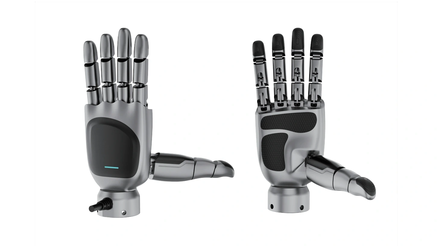
Go beyond two-finger open-and-close to coordinated multi-finger grasping. eHand-6 comes in left- and right-hand versions and drives five fingers through six control channels. It is an optional end effector for A7 and R1, for research on grasping policies, teleoperation mapping and manipulation data.
Data outputs, interface adaptation and delivery scope are confirmed per task.
The thumb has one lateral and one longitudinal channel, and the other four fingers each control flexion. Phalanges are mechanically linked, so each visible phalanx is not an independently actuated DOF.
Left and right hands can be configured for single- or dual-arm tasks. Mounting direction, range of motion and communication addresses are checked separately; a single-hand configuration does not include both hands.
Position and speed modes and up to 16 waypoints support motion research. Feedback includes status, faults and normalized position / speed, recorded with camera and arm timing.
SIX CHANNELS. COORDINATED MOTION.
The thumb handles opposition and flexion, while the other four fingers each control flexion. Combine motions per task to explore power grasps, pinches and gesture reproduction.
Linked structure: not every phalanx is independently actuated.
Send position, speed and maximum current percentage; store up to 16 waypoints for repeated motions and task-sequence research.
Record operating status, fault codes and normalized position / speed, paired with vision and arm state. Commands and readback values are kept separately.
LEFT / RIGHT · DIMENSIONS
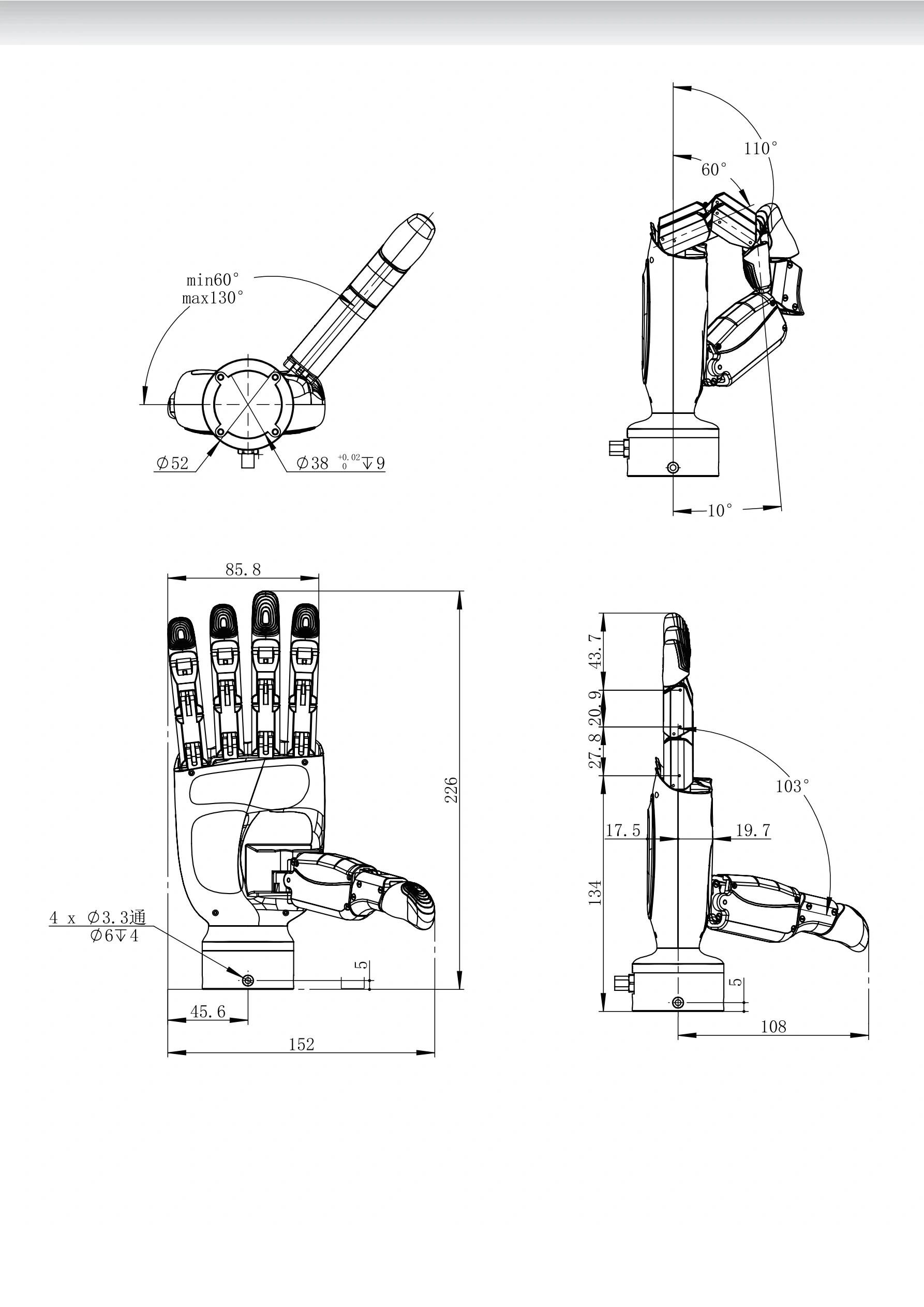
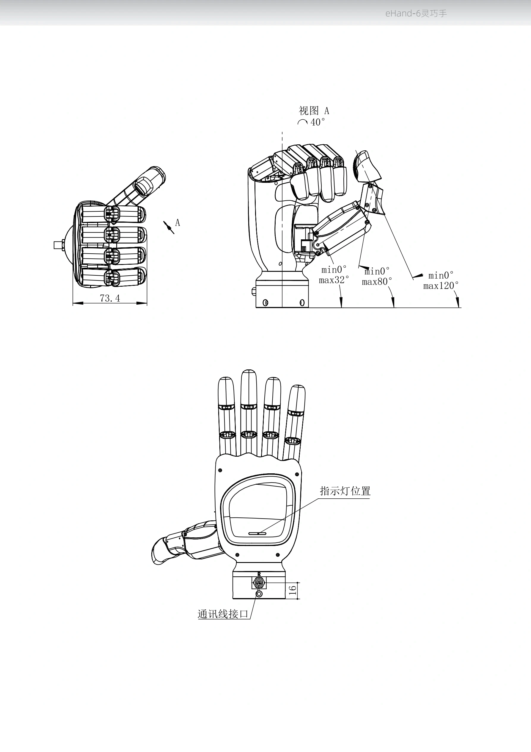
Original engineering drawings keep dimensions, tolerances and angle callouts. The rated envelope is 226 × 88 × 52 mm; actual designs must also account for thumb spread, adapters and cables.
Source: eHand-6 brushless version manual, printed pages 03–06. For selection discussions; use the formal engineering drawings and models for your hardware version for machining and collision checks, and do not measure from web images.
A7 × R1 × END EFFECTOR
Mechanical, electrical, control and data links are adapted separately, making the dexterous hand a verifiable end-effector module.
Mechanical adapter
Design the adapter from the left/right hand engineering drawings, confirming hole positions, fastening and cabling. Finger spread and wrist pose are included in collision checks; a similar outline does not mean direct compatibility.
Power and bus
A7 uses DC 48 V and CAN 2.0; the dexterous hand uses 24 VDC ±10% and CAN FD. Matching power and communication channels are configured separately and coordinated in software by the host.
End payload
Hand, flange, cables and workpiece all count toward the A7 end payload, with center of gravity and torque checked. The hand's 5 kg rated pull load does not override the A7's 3 kg end-payload limit.
Teleoperation & data
Gloves, vision or other inputs need motion mapping, limits and calibration. Target commands, normalized feedback and task results are recorded separately; human pose is never taken as ground-truth execution.
Home all joints at first power-on, and validate direction, limits and stopping behavior at low speed with no load before experimenting with objects.
Explore the R1 modular platformTHE DETAILS MATTER
Key eHand-6 brushless specifications and communication notes below.
| Parameter | Spec / configuration |
|---|---|
| Model / version | eHand-6 / brushless; protocol chapter applies to V2.0 |
| Options | Left hand / right hand; quantity per project |
| Degrees of freedom | 6: thumb lateral, thumb longitudinal, index, middle, ring, little finger |
| Weight | 715 g |
| Outline dimensions | 226 × 88 × 52 mm |
| Finger flexion angles | 60° + 110° + 170° (linked phalanges) |
| Thumb flexion angles | 32° + 44° + 44° (linked phalanges) |
| Thumb lateral angle | 70° |
| Motion cycle | 1.1 s to complete a gesture |
Source: manual printed pages 01–06. Rated outline dimensions are not the full motion envelope; thumb spread, cables and adapters must be checked separately. 1.1 s is not communication or control latency.
| Parameter | Spec / configuration |
|---|---|
| Max thumb grip force | 10 N (manual spec table) |
| Max finger grip force | 10 N (as stated in the manual spec table; whole-hand force not extrapolated) |
| Pull load | 5 kg (dexterous hand manual rating, not A7 / R1 carrying capacity) |
| Base version force control | The FAQ states the base version has no force-control sensor and cannot precisely control grip force |
| Tactile option | The manual lists a five-channel tactile feedback sensor option; not part of the base version by default |
| Current limit | The control parameter is a maximum current percentage, not a closed-loop grip-force setpoint in N |
Source: manual printed pages 01–02, 22. Output fields, sampling rate, calibration and closed-loop capability of the tactile option must be validated on the actual optional version; option descriptions do not apply to the base version.
| Parameter | Spec / configuration |
|---|---|
| Operating voltage | 24 VDC ±10% |
| Bus | CAN FD / FDCAN |
| Arbitration / data phase | 1 Mbps / 5 Mbps |
| Default communication ID | Right hand 0x11 / left hand 0x12 / broadcast 0x10 |
| Control data length | 32-byte application control frame; CAN FD transport up to 64 bytes |
| Termination resistor | The manual states a built-in 120 Ω; check termination against the actual bus topology |
| Development interfaces | The manual lists Python / ROS APIs; delivered version and examples confirmed per configuration |
Source: manual printed pages 07–19, 22. A CAN FD-compatible host interface is required; A7's CAN 2.0 and the hand's bus cannot be treated as one compatible interface.
| Parameter | Spec / configuration |
|---|---|
| Motion modes | Position control / speed control / open / close / home |
| Waypoints | Up to 16 waypoints, saved and executed |
| Channel control values | Normalized position, speed, maximum current percentage |
| Feedback fields | Operating status, fault codes, normalized position and speed |
| Recommended status polling | The manual recommends 10–100 ms intervals; not a validated control frequency or end-to-end latency |
| Position mode deadband | The manual requires the target to differ from the current position by more than 3%; fine step accuracy is not promised |
| First start-up | Home each node before executing motions |
Source: manual printed pages 08–22. Normalized feedback is not measured joint angle, nor ground-truth contact force. Protocol stop commands do not replace system hardware emergency stops and risk controls.
BUILD YOUR NEXT SETUP
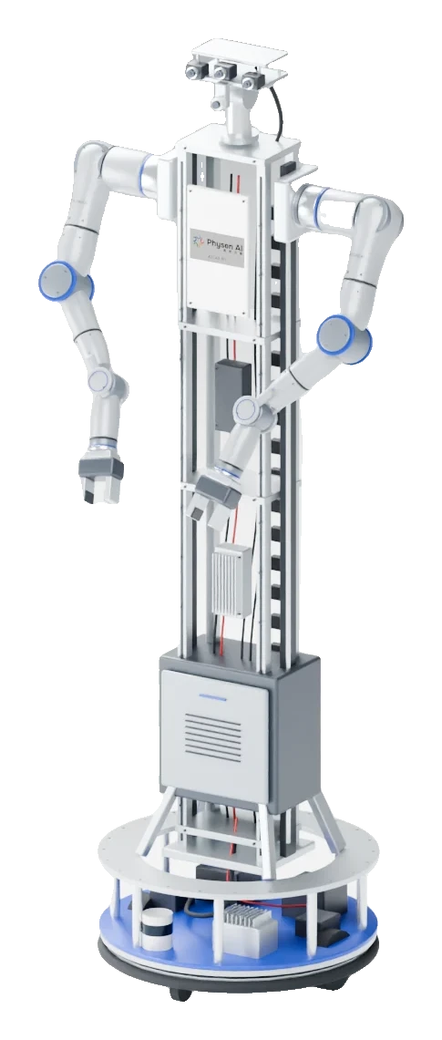
MODULAR / ROBOT LEARNING
Modular platform
7-AXIS / RESEARCH MANIPULATOR
Configured per project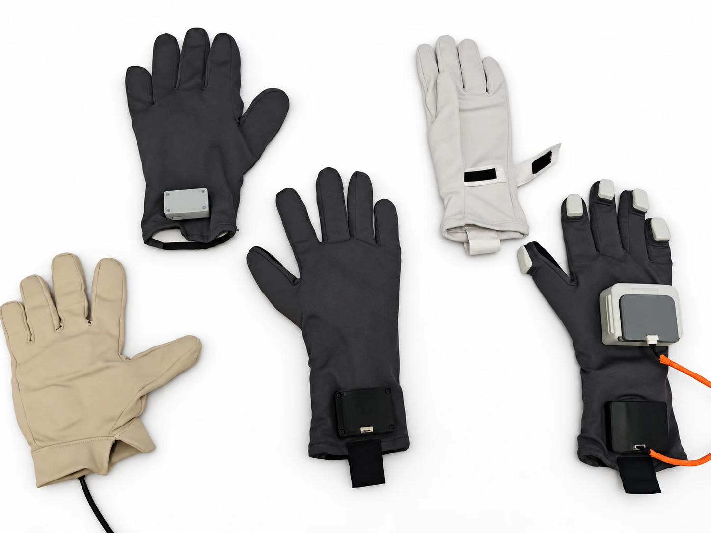 Tactile Data Glove
TACTILE / ELECTROMAGNETIC TRACKING
Multiple configurationsSTART WITH YOUR TASK
From device selection to data and training workflows, we'll help you find the right place to start.